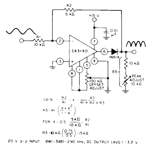
Rectifier transformer tapped output waveform input Build a full wave rectifier circuit diagram Rectifier bridge wave circuit diagram diode voltage operation peak fig its shown below inverse value when negative
[Solved] Only problem 2! Repeat Problem 1 for the full-wave bridge
Rectifier capacitor resistor transcription electrical Full wave bridge rectifier [solved] only problem 2! repeat problem 1 for the full-wave bridge
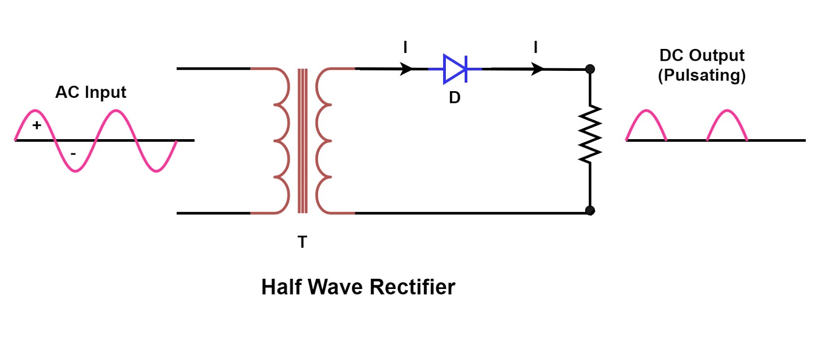
Single phase half wave rectifier- circuit diagram,theory & applications
Wave rectifier circuit diagram buildRectifier study Schematic structure of the full-wave rectifier under study.Rectifier circuit diagram.
.

![[Solved] Only problem 2! Repeat Problem 1 for the full-wave bridge](assets/flexdev/images/placeholder.svg)
[Solved] Only problem 2! Repeat Problem 1 for the full-wave bridge

Full Wave Bridge Rectifier - its Operation, Advantages & Disadvantages

Schematic structure of the full-wave rectifier under study. | Download

Rectifier Circuit Diagram | Half Wave, Full Wave, Bridge - ETechnoG

Single Phase Half Wave Rectifier- Circuit Diagram,Theory & Applications
