Question:- (a) in the following diagram, is the junction diode forward Output dc rectifier bridge input waveforms diode Rectifier waveform uncontrolled half output inductive resistive factor
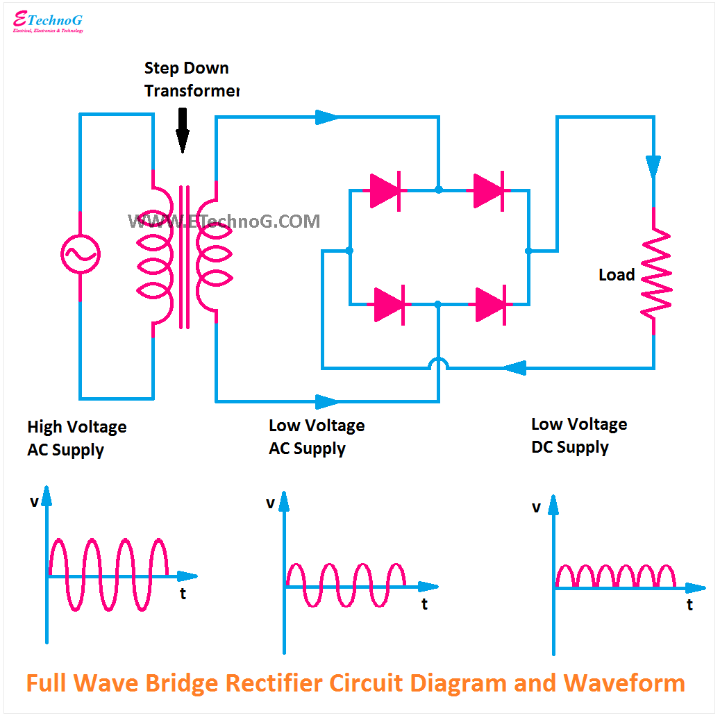
Full Wave Bridge Rectifier Circuit Working and Application
Rectifier tapped waveforms centre equations principle watelectrical Rectifier circuit diagram What is bridge rectifier ?
Rectifier wave waveform
Full-wave bridge rectifier (uncontrolled)Wave rectifier pulsating converts Rectifier circuit diagramFull-wave rectifier output waveform.
Center-tapped full wave rectifier : definition, principle & benefitsElectrical standards: full wave rectifier; full wave bridge rectifier What is 3 phase rectifier ?Full wave bridge rectifier – circuit diagram and working principle.

The full-wave bridge rectifier
Rectifier circuit waveform inputRectifier wave waveform output full electronics tutorials gif Wave bridge rectifierSix-pulse full-bridge rectifier: firing angle vs output voltage.
Rectifier bridge circuit diagram phase full half pulse six output wave voltage diode angle rectification firing each figure vs diodesFull wave bridge rectifier || electronics 1 || bangla Rectifier bridge working advantagesFull wave rectifier.

Full wave bridge rectifier circuit working and application
Rectifier wave full bridge characteristics circuit application working5730 smd help. Rectifier wave full bridge circuit diagram diode working draw simple operation diodes contents its works four reverse circuitsRectifier wave bridge capacitor smoothing output waveform will standards electrical increase dc above.
Rectifier output dc wave bridge waveform full circuit diagram voltage input principle working positive converts acRectifier transformer tapped output waveform input Rectifier wave full circuit bridge voltage output working transformer tapped centre across load advantages consists.


Six-pulse full-bridge rectifier: firing angle vs output voltage - Page 1

What is 3 Phase Rectifier ? - 3 Phase Half Wave, Full Wave & Bridge

Full Wave Bridge Rectifier – Circuit Diagram and Working Principle

Center-Tapped Full Wave Rectifier : Definition, Principle & Benefits

Full Wave Bridge Rectifier || Electronics 1 || Bangla - YouTube

5730 SMD help. - Page 2 - The Planted Tank Forum

Rectifier Circuit Diagram | Half Wave, Full Wave, Bridge - ETechnoG

Full-wave Rectifier Output Waveform | Basic Electronics Tutorials

Question:- (a) In the following diagram, is the junction diode forward
